
| Speed: 100 |
|
Angle : $\theta$ = 80 degree |
Joint position : $L_1/L$ = 0.35 |
Principal Moments of Inertia : $I_X =$ $ML^2$ $I_Y =$ $ML^2$ $I_Z =$ $ML^2$ |
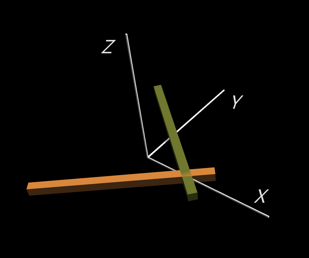
In the initial setting, the unstable axis is horizontal (or $X$-axis in the body fixed co-ordinate). Everytime the angular velocity vector $\vec\omega$ changes from the $+X$ direction to the $-X$ direction, or vice versa, the rigid body changes its orientation, but the direction of the rotation stays roughly the same.
The unstable axis of rotation is determined by the sequence of three principal moments of inertia, and it varies with the angle and the crossing point of the two rods in the simulator. You can find out by yourself that the unstable axis is actually the axis with the second largest principal moment.
In this simulator,
the display buttons constol on-off of the display of
the following:
| white axises | Principal Inertia Axises |
| white mesh of ellipsoid | Inertia Ellipsoid |
| white mesh of plane | Invariable Plane |
| small white sphere | Center of Mass |
| red arrow | Angular Momentum Vector $\vec L\,\big(\sqrt{2K}/L^2\big)$ |
| yellow arrow | Angular Velocity Vector $\vec\omega/\sqrt{2K}$ |
| green curve | Trajectory on the invariable plane |
| yellow curve | Trajectory on the inertia ellipsoid |
The inertia ellipsoid represents the curved surface where the rotation kinetic energy is constant, and the invariable plane represents the plane perpendicular to the angular momentum vector. As the rigid body rotates, the inertia ellipsoid rolls on the constant invariable plane without slipping. The angular velocity vector $\vec\omega$ points at the contact point between the inertia ellipsoid and the invariable plane.
The trajectory of the contact point on the invariable plane is represented by the green curve, and on the inertia ellipsoid by the yellow curve. You can find that the yellow curve forms a simple closed curve, thus this apparent complicated motion can be represented as a simple periodic motion on the ellipsoid. In general, however, the period on the ellipsoid is not commensurate with the period of the rolling motion of the ellipsoid itself, thus the green curve fills a annular region on the plane, and the motion is not periodic.